TM-5-5420-202-10 - Page 370 of 535
0055
TM 5-5420-202-10
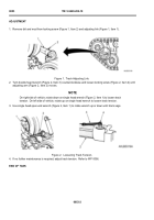
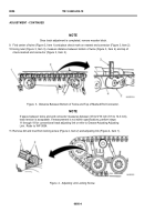
2. If outer pins (Figure 4, Item 4) are too far apart to attach track f xtures, wedge crowbar (Figure 4, Item 2)
between two center guides (Figure 4, Item 3) and groove of compensating idler wheel (Figure 4, Item 1). Pull
down on crowbar until track f xtures can be attached.
3. Remove crowbar (Figure 4, Item 2) from track center guide (Figure 4, Item 3).
Figure 4.
Connecting Track.
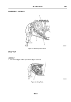
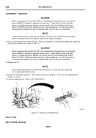
4. Line up track pins (Figure 5, Item 3) on outside of track.
5. Other two crew members attach track f xture (Figure 5, Item 5) to track pins (Figure 5, Item 3), and use ratchet
to turn track f xture tension adjustment (Figure 5, Item 1) counterclockwise to tighten.
6. Align track pins (Figure 5, Item 3) on inside of track and attach second track f xture (Figure 5, Item 5) to
inner pins.
7. Tighten both track f xtures (Figure 5, Item 5) by turning tension adjustment (Figure 5, Item 1) counterclockwise
until track links (Figure 5, Item 4) are almost touching.
NOTE
Use new center guide bolt and nut, if available. If not, replace as soon as possible.
8. Install outer and inner connectors (Figure 5, Item 2) (WP 0049) and center guide. Refer to WP 0050.
Figure 5.
Adjusting Track Fixtures.
0055-4
ASSEMBLY - CONTINUED
Back to Top

