TM-5-5420-202-10 - Page 376 of 535
0056
TM 5-5420-202-10
NOTE
Once track adjustment is completed, remove wooden block.
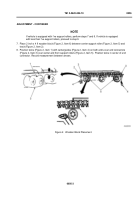
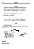
9. Find center of twine (Figure 3, Item 1) and place check mark on nearest end connector (Figure 3, Item 2).
10.Using ruler (Figure 3, Item 3), measure distance between bottom of twine (Figure 3, Item 4) and top of
check-marked end connector (Figure 3, Item 2).
Figure 3.
Distance Between Bottom of Twine and Top of Marked End Connector.
NOTE
If space between twine and end connector measures between 3/8 to 9/16 inch (9.5 to 14.3 mm),
track tension is acceptable. If measurement is not within specifications, perform steps
11 through 18 for conventional track adjusting link or refer to Grease-Actuating Adjusting
Link. Refer to WP 0054.
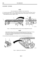
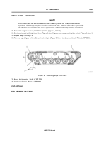
11. Remove dirt and mud from locking screw (Figure 4, Item 2) and adjusting link (Figure 4, Item 1).
Figure 4.
Adjusting Link Locking Screw.
0056-4
ADJUSTMENT - CONTINUED
Back to Top


