TM-5-5420-202-10 - Page 371 of 535
TM 5-5420-202-10
0055
NOTE
Field mechanic must torque end connector and center guide bolts to correct torque value. If
f eld mechanic is not available, perform steps 9 through 24. Notify f eld mechanic to torque
end connector and center guide bolts as soon as possible.
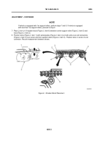
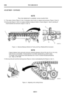
9. Turn center guide nut (Figure 6, Item 1) counterclockwise one turn to loosen.
10.Start engine. Refer to WP 0015.
11. Move vehicle until end connector (Figure 6, Item 2) is located at 9 o’clock position in reference to compensating
idler wheel (Figure 6, Item 3). Stop vehicle. Refer to WP 0016.
12.Move shift lever to P (Park). Refer to WP 0013.
Figure 6.
Remove Center Guide Nut.
13.Raise and hold ENGINE FUEL SHUTOFF switch until engine stops. Refer to WP 0015.
14.Set parking brake. Refer to WP 0012.
15.Tighten inner and outer connector bolts. Refer to WP 0049.
16.Start engine. Refer to WP 0015.
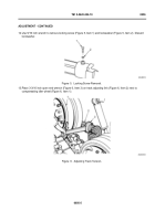
17.Move vehicle until end connector (Figure 7, Item 2) is located at 6 o’clock position in relation to compensating
idler wheel (Figure 7, Item 1).
Figure 7.
Engine Fuel Shutoff Switch.
0055-5
ASSEMBLY - CONTINUED
Back to Top

