TM-5-5420-202-20-1 - Page 642 of 1020
NO
DETAILED TROUBLESHOOTING PROCEDURE
VEHICLE OPERATION – HULL POWER
(Continued)
Symptom-31.1
TM 5-5420-202-20-1
Change 6
4-414.21
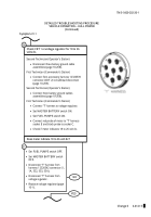
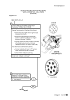
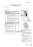
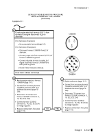
First Technician (Commander’s Station)
•
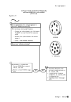
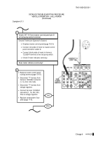
Displace front accessory harness 12326538
connector at bulkhead disconnect (page 10-
269).
•
Connect jumper wire from contact C (CKT 534)
of harness 12326542 to contact L (CKT 533).
•
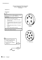
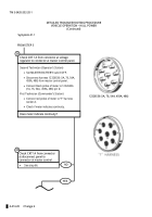
Connect red probe of meter to "T" harness
socket B and black probe to socket D.
•
Check if meter indicates continuity.
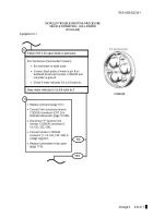
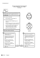
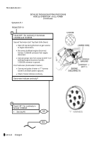
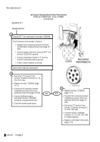
Check CKTs 533 and 534 for continuity in
harness 12326542.
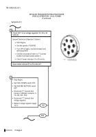
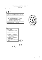
Does meter indicate continuity?
40
•
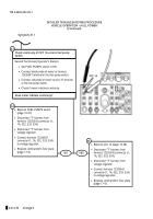
Disconnect “T” harness from
harness 12326542 connector (1, 1A,
532, 533, 534)
.
•
Replace harness 12326542 (page
10-1).
•
Connect front accessory harness
12326539 connector (CKT 2) to
bulkhead disconnect (page 10-269).
41
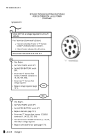
YES
•
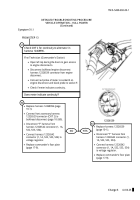
Replace harness 12326538
(page 10-1).
•
Connect front accessory harness
12326539 connector (CKT 2) to
bulkhead disconnect (page 10-
269).
•
Disconnect “T” harness from
harness 12326542 connector (1,
1A, 532, 533, 534)
.
•
Connect harness 12326542
connector (1, 1A, 532, 533, 534)
to voltage regulator.
•
Replace commander’s floor plate
(page 17-9)
42
FROM STEP 36
12326542
Back to Top

