TM-5-5420-202-20-2 - Page 241 of 734
TM 5-5420-202-20-2
FUEL PUMP TO FUEL-WATER SEPARATOR HOSE ASSEMBLY REPLACEMENT (Sheet 5 of 5)
NOTE
It may be necessary to perform steps 6 and 7 several
times until a constant fuel flow (no bubbles) from
the bleed cap (A) is observed. Two persons will be
required to perform steps 3 through 11.
3.
4.
5.
6.
Station one person in driver’s compartment to operate switches.
Set fuel pumps switch to ON position (TM 5-5420-202-10).
Set MASTER BATTERY switch to ON position (TM 5-5420-202-10).
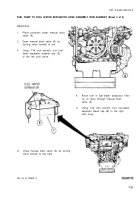
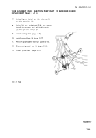
Second person, watch fuel-water separator bleed cap (A) until air release (bubbles)
appear, then have first person set MASTER BATTERY switch to OFF.
7.
8.
9.
10.
11.
12.
13.
Wait about one minute and repeat step 5 until a constant bubble free flow is observed
at bleed cap (A).
Second person, using 7/16 inch wrench, turn fuel-water separator bleed cap (A) to the
right until snug.
Check for leaks. Tighten or replace components as necessary.
Perform operational check of automatic drain (page 7-223).
Set MASTER BATTERY switch to OFF position (TM 5-5420-202-10).
Disconnect engine from powerplant ground hop (page 5-40).
Install powerplant (page 5-14).
End of Task
7-24
Back to Top

