TM-5-5420-202-20-2 - Page 516 of 734
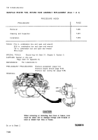
MANIFOLD HEATER IGNITION COIL AND CABLE REPLACEMENT (Sheet 3 of 3)
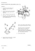
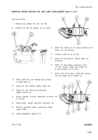
INSTALLATION:
1.
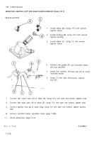
Position two clamps (A) onto coil (B).
2.
Position coil (B) and clamps (A) on frame.
3.
4.
5.
6.
7.
8.
9.
10.
11.
12.
13.
14.
TM 5-5420-202-20-2
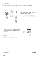
Install two screws (C) to secure clamps (A) to
frame. Do not tighten.
Connect cable
Using 7/8 inch
connector.
Using 1/2 inch
(D) to coil (B).
wrench, tighten cable (D)
socket, extension, and
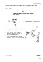
1/2 inch wrench, install two screws (E)
to hold bracket (F) to frame.
Using 7/16 inch socket, install two screws
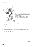
Route cable (D) over bracket and connect
to spark plug (J).
Using 3/4 inch wrench, tighten cable (D).
Using 1/2 inch socket and extension,
tighten screws (C).
Alining keyway, connect electrical connector (K)
to coil (B).
Using pliers, tighten electrical connector (K).
Perform manifold heater operational check
(page 7-288).
Install powerplant (page 5-14).
(G) and clamp (H) to bracket (F).
End of Task
7-281
Back to Top

