TM-5-5420-202-20-3 - Page 108 of 1060
TM 5-5420-202-20-3
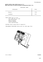
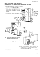
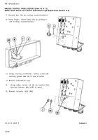
MASTER CONTROL PANEL REPAIR (Sheet 34 of 73)
Circuit Breaker Replacement (Sheet 2 of 7)
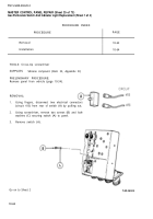
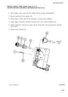
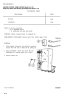
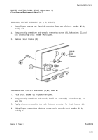
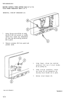
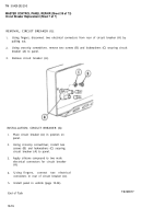
REMOVAL; CIRCUIT BREAKERS (A, B, C, AND E):
1.
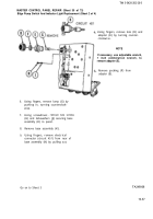
Using fingers, remove two electrical connectors from rear of circuit breaker (A) by
pulling out.
2.
Using cross-tip screwdriver and wrench, remove two screws (B), lockwashers (C), and
nuts (D) securing circuit breaker (A) to panel.
3.
Remove circuit breaker (A).
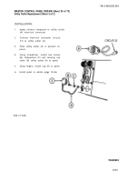
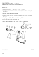
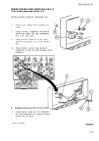
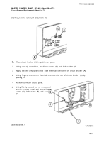
INSTALLATION; CIRCUIT BREAKERS (A,B,C, AND E):
1.
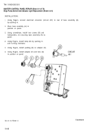
Place circuit breaker (A) in position on panel.
2.
Using cross-tip screwdriver and wrench, install two screws (B), lockwashers (C), and
nuts (D).
3.
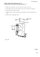
Apply silicone compound to two male electrical connectors for circuit breaker (A).
4.
Using fingers, connect two electrical connectors in rear of circuit breaker (A) by
pushing in.
Go on to Sheet 3
TA249012
10-71
Back to Top

