TM-5-5420-202-20-3 - Page 746 of 1060
TM 5-5420-202-20-3
PARKING BRAKE CONTROL ASSEMBLY (ONE PIECE OR FRONT SECTION) AND LINKAGE REPLACEMENT
(Sheet 16 of 17)
NOTE
If installing one-piece control, omit next two steps. if installing front section of two-piece control,
do next two steps then go to step 42.
31.
32.
33.
34.
35.
36.
37.
38.
39.
40.
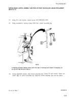
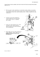
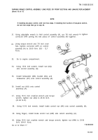
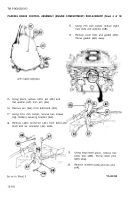
Using adjustable wrench to hold control assembly (A), use 7/8 inch wrench
connector (AP) joining the two pieces of control assembly (A) together.
Using torque wrench and 7/8 inch crow-
foot, tighten connector (AP) on control
assembly (A) to 35-50 lb-in. (8.9 - 12.7
N.m).
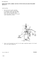
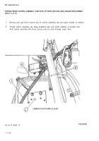
Go to engine compartment.
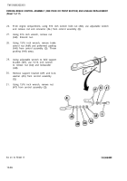
Using 15/16 inch wrench, install nut (AQ)
onto control assembly (A).
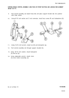
Install lockwasher (AR), bracket (AS), and
lockwasher (AT) onto control assembly (A).
Install nut (AU) onto control
assembly (A).
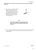
Using 15/16 inch crowfoot wrench and torque
wrench, tighten nut (AQ) to 45-50 lb-ft.
to tighten
(61-68 N.m).
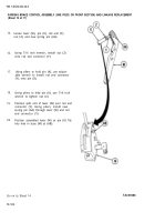
Using 15/16 inch wrench, install brake control nut (AX) onto control assembly (A).
Using fingers, install brake control nut (AW) onto control assembly (A).
Using 15/16 inch crowfoot wrench and torque wrench, tighten nut (AW) to 25-30
lb-ft. (34-41 N.m).
Go on to Sheet 17
TA249489
13-105
Back to Top

