TM-5-5420-203-14 - Page 67 of 298
TM 5-5420-203-14
c. Assembly of the Bridge Separated into Eight Sections - CONT
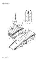
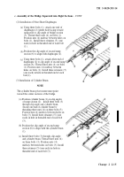
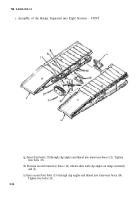
(6) Flexible Hydraulic Hose Connections.
(a)
(b)
(c)
(d)
Position a female center section on the left
timbers with about 1 ft distance between
the ends of the ramp and center sections.
Attach remaining end of flexible hose (1)
to hydraulic line (3) located on center
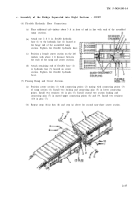
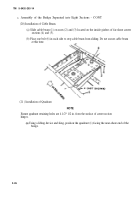
Place additional crib timbers about 3 ft in front of and in line with each of the assembled
ramp sections.
Attach one 2 ft 8 in. flexible hydraulic
hose (1) to the hydraulic line (2) located at
the hinge end of the assembled ramp
section. Tighten the flexible hydraulic hose.
section. Tighten the flexible hydraulic
hose.
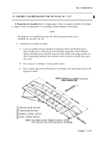
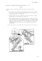
(7) Pinning Ramp and Center Sections.
(a)
(b)
Position center section (1) with connecting points (2) mating with connecting points (3)
of ramp section (4). Install two locking and connecting pins (5) in lower connecting
points. Install two retainers (6) in pin (5). Install second two section locking and
connecting pins (7) in mated upper connecting points (8) and (9). Install two retainers
(10) in pins (7).
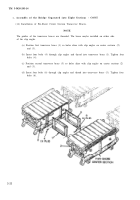
Repeat steps (6)(a) thru (d) and step (a) above for second near-shore center section.
2-17
Back to Top


