TM-5-5420-203-14 - Page 71 of 298
TM 5-5420-203-14
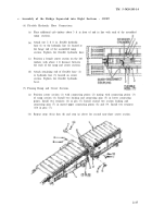
c. Assembly of the Bridge Separated into Eight Sections -
CONT
NOTE
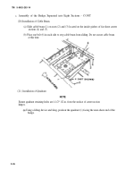
Some side to side and up and down movement maybe required to aline hinge points for
pinning.
(b)
(c)
(d)
(e)
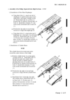
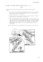
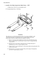
The two center section locking pins have lubrication fittings and are used on the outside
end connectors at the bottom of the hinge joint Install two center section hinge pins (1)
through connecting points (2) (Outside View).
Install two retainers (3) in pins (l). Install top center section pin connector (4) through
connecting points (5). Install retainer(6) in connector (4).
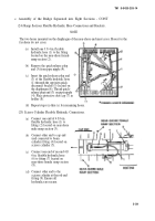
Install two quadrant hinge pins (7) in the inside connectors (8) of center sections (9) and
(10) so that the hole for the quadrant locking pin retraining hole (11) is located toward the
middle area between the two sections (Inside View). For ease of installation of quadrant,
retaining hole (11) must run from the 10:30 to the 4:30 position (45° in reference to the
ground). Retaining hole (11) must be 4 1/2 ± 1/2 in. from the surface (8) of center
section hinges.
Insert pin connector (12) in connector points (13). Install retainer (14) in connector (12).
2-21
Back to Top


