TM-5-5420-203-14 - Page 68 of 298
TM 5-5420-203-14
c. Assembly of the Bridge Separated into Eight Sections - CONT
(8)
(9)
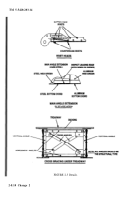
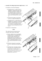
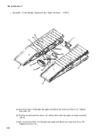
Installation of Scissor Cylinder Supports,
(a) Using two threaded bolts (l), secure lower
cylinder support (2) in position between
the two center sections (3) and (4) as shown
(b) The second scissor cylinder support (5)
will be installed after scissor cylinder by
attaching to sections (3) and (4) and
securing with two bolts (6).
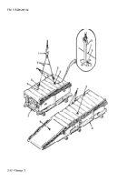
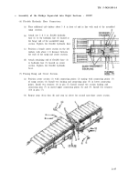
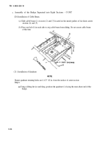
Installation of Scissor Cylinder.
The scissor cylinder is heavy. Use care when lifting to prevent injury. Stay out from under
the scissor cylinder at all times.
(a)
Remove
protective cup (if used) from threads of rod end (1) of scissor cylinder (2).
Thread clevis (3) on threads of rod end (l).
(b)
(c)
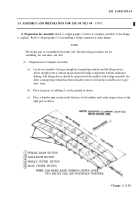
Lift scissor cylinder (2) using a lifting device and center over lower cylinder support (4).
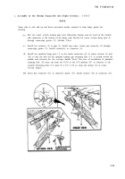
Lower scissor cylinder (2) on lower cylinder support (4) while working into position for
mating. Slide unbolted transverse brace (see step (5)(c), reference item (3)) from clip
angles
over pin end of scissor cylinder. Pin scissor cylinder (2) to cylinder beam (5) using pin
(6)
(d)
(e)
2-18
and secure with two cotter pins (7).
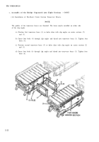
Refer to paragraph 2-3c(5)(c) and secure
Refer to paragraph 2-3c(8)(b) and install
transverse brace.
upper scissor cylinder support.
Back to Top

