TM-9-1240-401-34-P - Page 101 of 590
3-43
TM 9-1240-401-34&P
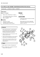
c. Installation
1
2
3
4
5
Install wiring harness (8) on side of reticle cage
assembly (7) and secure with clamp (10) and
machine screw (9).
Install reticle cage assembly (7) in housing (5) be-
ing careful not to damage wiring harness (8).
Install threaded ring (6) in housing (5) using fabri-
cated spanner wrench.
Apply grease to two new preformed packings (4)
and install in grooves of two access covers (3).
Install two covers (3) on housing (5) and secure
with eight new Iockwashers (2) and eight cap
screws (1).
3-26. WIRING HARNESS MAINTENANCE INSTRUCTIONS
This task covers:
a. Removal b. Disassembly c. Repair d. Assembly e. Installation
Soldering iron, electric (Item 24, appx F)
Reticle cage assembly removed, M118A3
Tool Kit, Electronic System, Repair, Field Mainte-
(ref. para 3-24)
nance(SC5180-95-CL-B29)
Reticle cage assembly removed, M118A2
(ref. para 3-25)
Level assembly removed, M118A3
Flux (Item 5, appx B)
(ref. para 3-18)
Level assembly removed, M118A32
Insulation sleeving (Item 16, appx B)
Solder (Item 18, appx B)
(ref. para 3-19)
Tape (Item 20, appx B)
Cover assembly removed, M118A3
(ref. para 3-16)
Cover assembly removed, M118A2
TM 9-254
(ref. para 3-17)
Back to Top


