TM-9-1240-401-34-P - Page 276 of 590
TM 9-1240-401-34&P
5.1-19. M15 QUADRANT MAINTENANCE INSTRUCTIONS - continued
c. Assembly - continued
NOTE
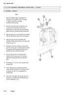
Steps 13 through 24 apply to replacement of
shouldered shaft assembly. Steps 25 through
31 apply to reinstallation of existing
13
14
15
16
17
18
19
20
shouldered shaft assembly.
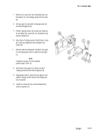
Slide ball socket seat (29) onto long end of new
shouldered shaft assembly (30) with internal
beveled portion of ball socket seat (29) positioned
against bearing of shouldered shaft assembly (30).
Slide spur gear (31) onto shouldered shaft assembly
(30) with raised portion of gear away from bearing.
Slide worm gear (32) onto shouldered shaft
assembly (30) with setscrew hole of worm gear (32)
facing spur gear (31).
Temporarily install two setscrews to secure worm
gear (32) and spur gear (31) tightly against shoulder
of shouldered shaft assembly (30) until holes for
tapered pins (33) are drilled and reamed.
Drill and ream two holes in shouldered shaft
assembly (30) for tapered pins (33). Remove
setscrews and apply grease (item 6, appx B) to
gears.
Remove gears (31 and 32) from shouldered shaft
assembly (30).
Install shouldered shaft assembly (30) and ball
socket seat (29) through boss on housing (10) and
install gears (32 and 31) on shouldered shaft
assembly (30).
Aline holes in worm gear (32) and spur gear (31)
with holes in shouldered shaft assembly (30) and
install two tapered pins (33).
5.1-42
Change 1
Back to Top

