TM-9-1240-401-34-P - Page 279 of 590
TM 9-1240-401-34&P
32
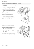
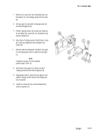
Insert shouldered shaft (37) into housing (10) from
rear of housing. Aline hole in shouldered shaft with
cutout in base of housing.
33
Install and tighten three screws (38) and three new
lockwashers (39).
34
35
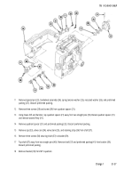
Install pin (40) in shouldered shaft (37), if removed.
Install electrical lead (41) into shaft by threading wire
of electrical lead into externally threaded opening of
shaft and out small hole that is alined with cutout in
housing (10).
36
Secure electrical lead (41) into shaft with setscrew
(42). Setscrew must not protrude from surface of
shaft.
37
Solder wire of electrical lead (41) to center post of
toggle switch (43) using solder (item 18, appx B) and
flux (item 5, appx B).
38
39
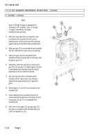
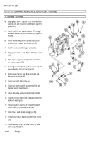
Install two machine screws (44) in gear sector (45).
Apply grease (item 6, appx B) to shaft and install flat
washer (46), gear sector (45), flat washer (47), and
nut (48).
40
Using tubular spanner wrench 1-1/16 and 1-5/64
inch, tighten nut (48) and secure with two setscrews
(49).
41
Apply grease (item 6, appx B) to plunger (50) and
spring (51).
42
Install plunger (50) and spring (51) into housing (10)
and secure with plug (52).
43
Position bracket (53) on housing (10).
NOTE
If shouldered shaft was removed from
housing, perform steps 32 thru 34. If
shouldered shaft was not removed, go to step
35.
Change 1
5.1-45
Back to Top


