TM-9-1240-401-34-P - Page 274 of 590
TM 9-1240-401-34&P
5.1-19 M15 QUADRANT MAINTENANCE INSTRUCTIONS - continued
c. Assembly
1
2
3
4
5
6
7
8
9
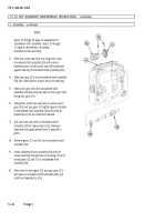
Apply grease (item 7, appx B) to new preformed
packing (1) and install in electrical bracket (2).
Solder terminals (3 and 4) to short electrical wire (5),
using solder (item 18, appx B) and flux (item 5, appx
B).
Secure terminal (3) to electrical bracket (2) with
screw (6).
Solder electrical wire (7) to terminal (8) and to center
post of toggle switch (9).
Assure that terminals (4 and 8) project from
electrical bracket (2). Position electrical bracket (2)
with preformed packing (1) on housing (10). Secure
with three screws (11) and three new lockwashers
(12).
Position new gasket (13) on electrical bracket (2)
and install two contacts (14) into insulator (15).
Attach two terminals (4 and 8) extending through the
hole in center of gasket (13) to two contacts (14)
with two nuts (16).
Position receptacle shell (17) with plate (18) inside
shell over two contacts (14). Seat receptacle shell
(17) against insulator (15) and install screw (19) and
shouldered pin (20).
Secure insulator (15) to electrical bracket (2) with
three screws (21) and three new lockwashers (22).
Apply sealing compound (item 13, appx B) to seal
the hole in center of electrical bracket (2).
5.1-40
Change 1
Back to Top


