TM-9-1240-401-34-P - Page 266 of 590
TM 9-1240-401-34&P
5.1-17 LEVEL ASSEMBLY MAINTENANCE INSTRUCTIONS - continued
c. Assembly
1
2
3
4
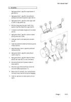
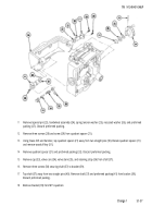
Using suitable pliers, bend detent tabs on level vial
covers (1 and 2) closer together or farther apart, as
required to obtain desired fit. Position level vial
covers (1 and 2) between bosses of bracket (3).
Install fire control levels (4 and 5) by sliding into
bracket (3) and into level vial covers (1 and 2).
Install eccentric bushings (6 and 7).
Install rings (8 and 9) into bracket (3) and tighten
rings snug against eccentric bushings (6 and 7)
using fabricated eccentric tool (fig. C-2, appx C).
d. Adjustment
NOTE
Install cross-level knob on M15 quadrant.
Install M15 quadrant on howitzer by
procedures described in TM 9-2350-311-20-2.
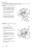
1
2
3
4
5
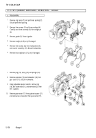
Level trunnions and gun tube as described in TM 9
2350-311-10.
Turn spur gear assembly (1) until correction
counters register 00 mils. Turn elevation handwheel
(2) until elevation counter registers 0000 mils.
Adjust elevation handwheel (2) to center bubble of
fire control level (3).
Loosen three screws (4) to disengage differential
spur gear (5) from spur gear shaft (6).
Rotate differential spur gear (5) to zero counter, then
tighten three screws (4).
5.1-32
Change 1
Back to Top


