TM-9-1240-401-34-P - Page 262 of 590
TM 9-1240-401-34&P
5.1-16. COVER ASSEMBLY MAINTENANCE INSTRUCTIONS - continued
b. Repair
1
Remove corrosion, grease, and dirt from all parts.
Refer to TM 9-254 for instructions.
2
Visually inspect for missing or damaged parts.
3
Repair or replace parts in accordance with
authorized parts listed in appendix D.
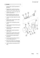
c. Assembly
1
2
3
4
5
If removed, install lens (1) using adhesive (item 1.1,
appx B).
If removed, insert electrical plug connector (2)
through front of cover (3) with raised brass portion of
contact toward front of cover. Using solder (item 18,
appx B) and flux (item 5, appx B), solder contact (4)
to end of electrical plug connector (2).
Assemble insulator plates (5 and 6) on each side of
contact (4) and install with two insulator bushings
(7), two new lockwashers (8), and two screws (9).
Seal electrical plug connector (2) to cover (3) in
three places by applying sealing compound (item 13,
appx B).
Using 1/2 and 33/64 inch tubular spanner wrench,
secure contact of electrical plug connector (2) with
externally threaded ring (10) and stake with
adhesive (item 2, appx B).
5.1-28
Change 1
Back to Top


