TM-9-1240-401-34-P - Page 263 of 590
TM 9-1240-401-34&P
6
7
8
9
10
11
12
13
14
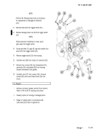
Tighten four screws (15).
Apply sealing compound (item 13, appx B) to the
flange on cover (3) where windows (11 and 12)
were removed. Position each window and press into
place. Remove excess sealing compound.
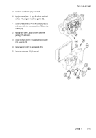
Pull wire (13) with lamp base through to the front of
overlay assembly (14).
Position overlay assembly (14) on cover (3).
Apply adhesive (item 2, appx B) to four screws (15).
Position identification plate (16) and identification
plate (17) and loosely secure with four screws (15).
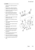
Using tubular spanner wrench, 11/16 inch and 45/64
inch, install retaining ring (18) and stake using
adhesive (item 2, appx B).
Insert lamp base portion of overlay assembly (14)
into contact of electrical plug connector (2).
Apply adhesive (item 2, appx B) to inside edge of
cap (19).
Install cap (19) and secure with two screws (20).
Remove any excess adhesive from outer edge of
cap (19).
Change 1
5.1-29
Back to Top

