TM-9-1240-401-34-P - Page 256 of 590
TM 9-1240-401-34&P
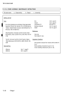
5.1-14. M15 QUADRANT MAINTENANCE INSTRUCTIONS - continued
c. Assembly - continued
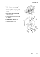
16
17
18
19
20
21
22
23
24
25
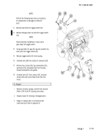
NOTE
Both correction counters and elevation
counter must be zeroed prior to installing knob
assembly.
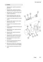
If removed, install two straight pins (23).
Apply grease (item 6, appx B) to new preformed
packing (24) and install into groove (25) of cover
assembly (14).
Position knob assembly (26) at the midway point
between stops (approximately 5-1/2 turns from one
stop).
Install base (27) on knob assembly (26).
Install knob assembly (26) with base (27) on cover
assembly (14) and secure with three screws (28)
and three new lockwashers (29).
If numbers of correction counter (30) do not aline
within 1/16 inch (1.588 mm), adjust two setscrews
(31) to aline numbers.
Check that upper correction counter (30) registers at
least +50 mils when knob assembly is turned
clockwise to stop. Check that lower correction
counter (30) registers at least -50 mils when knob
assembly is turned counterclockwise to stop.
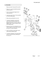
If removed, install spring tension clip (32) and plate
spacer (33) on housing and secure with two screws
(34).
If removed, install identification plate (35) and two
screws (36) on housing.
If removed, install instrument light (37).
5.1-22
Change 1
Back to Top


