TM-9-1240-401-34-P - Page 287 of 590
TM 9-1240-401-34&P
26
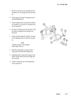
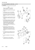
Remove four screws (17), four lockwashers (18),
and rotating counter (15) from base (4).
CAUTION
When drilling correction counter, extreme care
must be exercised to prevent damage to
rotating counters.
27
Finish drilling two holes in rotating counter (15) for
two straight pins (16) and drill shaft of rotating
counter (15) for straight pin (19). Install straight pin
(19) to secure spur gear (14) to shaft of rotating
counter (15).
28
Position rotating counter (15) on base (4) and install,
but do not tighten four screws (17) and four
lockwashers (18).
29
Aline holes in rotating counter (15) with holes in
base (4). Install two straight pins (16) and tighten
four screws (17).
30
Remove setscrew temporarily installed in spur gear
(14).
NOTE
If correction counter is to be reinstalled,
perform steps 31 thru 33.
31
Aline holes of spur gear (14) to holes in shaft of
rotating counter (15) and install straight pin (19).
32
Install rotating counter (15) over two straight pins
(16) and install four screws (17) and four new
lockwashers (18).
33
Apply grease (item 6, appx B) to spur gear (14).
34
Rotate spur gearshaft (10) and check that counters
operate smoothly without binding.
Change 1
5.1-53
Back to Top


