TM-9-1240-401-34-P - Page 293 of 590
TM 9-1240-401-34&P
c. Assembly
1
2
3
4
5
6
7
8
9
10
11
12
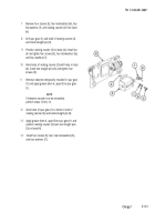
Install light lens (1), flat end first, into bracket (2).
Feed wire lead through small hole in bracket (2) and pull snug, drawing electrical connector (3) into lamp recess with
raised portion facing outward.
Install contact (4) with two new lockwashers (5) and two screws (6).
Using solder (item 18, appx B) and flux (item 5, appx B), solder lead of electrical connector (3) to contact (4).
Using tubular spanner wrench 11/16 inch and 45/64 inch, install ring (7) into bracket (2).
Perform continuity check from electrical connector (3) to contact (4).
Install spacer (8) onto LED (9). Install LED (9) with spacer (8) and electrical cover (10). Secure with screw (11) and
new lockwasher (12).
If removed, install two pins (13).
NOTE
It may be necessary to bend detent tabs on level vial covers with suitable pliers prior to installation of covers in
level assembly.
Install two level vial covers (14) between bosses of bracket (2).
Install fire control levels (15 and 16) by sliding into bracket (2).
Install eccentric bushings (17 and 18).
Install rings (19 and 20) into bracket (2) and tighten rings snug against eccentric bushings (17 and 18), using fabricated
eccentric tool (fig. C-2, appx C).
Change 1
5.1-59
Back to Top


