TM-9-1240-401-34-P - Page 295 of 590
TM 9-1240-401-34&P
a.
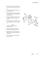
SETTING UP AND ADJUSTING CROSS-LEVELING FIXTURE
1
2
3
4
Secure cross-leveling fixture (1) on a solid stand
bolted to the floor.
Place precision level (2) on square portion of
elevation shaft (3), perpendicular to axis of rotation,
and center the bubble.
Place precision level (2) on square portion of
elevation shaft (3), parallel to axis of rotation, and
center the bubble.
Set cant vernier scale (4) and elevation vernier scale
(5) to zero.
5
Install test fixture adapter (6) on shaft of cross-
leveling fixture (1).
6
Tighten eight cap screws (7) only enough to keep
test fixture adapter (6) from moving while checking
test fixture adapter (6) for level.
7
Using a 5-second level or known good gunners
quadrant and 6-inch parallel bar positioned on flat
surface of round block (8), loosen eight cap screws
(7) only enough to gently tap test fixture adapter (6)
until bubble in level vial or gunner’s quadrant is
centered.
8
Using a 5-second level or known good gunners
quadrant and a 6-inch parallel bar on square portion
of elevation shaft (3), turn upper section handwheel
(elevation) (9) and lower handwheel (cross-level)
(10) until square portion of elevation shaft (3) is
leveled in both elevation and cross-level positions.
9
With gunners quadrant still positioned as in step 7,
ensure that surface is still level.
Change 1
5.1-61
Back to Top

