TM-9-1240-401-34-P - Page 286 of 590
TM 9-1240-401-34&P
5.1-20. COUNTER ASSEMBLY MAINTENANCE INSTRUCTIONS - continued
c. Assembly - continued
15
16
17
18
19
20
21
22
23
24
25
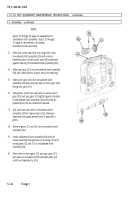
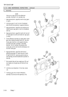
Apply grease (item 6, appx B) in hole of boss on
base (A) and hole of bracket(B).
Slide spur gearshaft (10) through boss of base (A)
and slide retaining ring (11) on shaft of spur
gear-shaft (10), being careful to spread retaining ring
(11) only as far as necessary.
Position spur gear (12) so that teeth of spur gear
mesh with gear of differential assembly (8) and slide
shaft of spur gearshaft (10) through spur gear (12)
and into hole of bracket (B).
Secure spur gearshaft (10) in base (4) with retaining
ring (11).
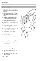
Aline holes of spur gear (12) with hole in spur
gearshaft (10) and secure with tapered pin (13).
Apply grease (item 6, appx B) to spur gear (12) and
to teeth of spur gearshaft (10).
NOTE
If correction counter is to be replaced, perform
steps 21 thru 30. If existing counter is to be
reinstalled, go to step 31.
Slide spur gear (14) on shaft of rotating counter (15)
and temporarily install, but do not tighten a setscrew
in spur gear (14).
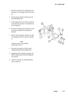
Remove two straight pins (16) from base (4).
Position rotating counter (15) on base (4) and install,
but do not tighten four screws (17) and four new
lockwashers (18).
Aline spur gear (14) with teeth of spur gearshaft (10)
and temporarily secure spur gear (14) to shaft of
rotating counter (15) with setscrew. Tighten four
screws (17).
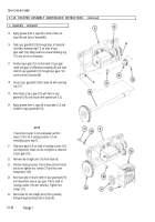
Mark holes for two straight pins (16) by partially
drilling through existing holes in base (4).
5.1-52
Change 1
Back to Top

