TM-9-1240-401-34-P - Page 304 of 590
5. 1-24. M15
TM 9-1240-401-34&P
1
2
3
4
5
6
7
8
9
10
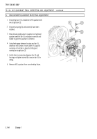
Rotate handwheel assembly (1) at least 100 mils in each direction and check that backlash is not more than 0.5 mil.
If backlash exceeds 0.5 mil, adjust plug (2).
Using tape (item 20, appx B), tape a pointer to right side of housing (3) in line with cross-level knob (4).
With bubble of cross-level fire control level (5) centered, place a piece of tape on side of cross-level knob (4) and scribe
a mark on the tape in line with pointer for a reference point.
Rotate cross-level knob one complete revolution in each direction and back to point where pointer and scribe mark on
tape were originally alined.
Bubble of fire control level (5) must recenter within 1/2 graduation (0.5 mil).
Using known good gunner's quadrant (6), place 300 mils on gunner's quadrant.
Place gunner’s quadrant on square shaft of cross-leveling fixture and turn lower handwheel (7) counterclockwise until
quadrant bubble centers. Turn cross-level knob (4) to center bubble of fire control level (5).
Repeat step 5. Fire control level must center within 1/2 graduation (0.5 mil).
Repeat step 7 in a clockwise direction.
Repeat step 8.
Fire control level must center within 1/2 graduation (0.5 mil).
5.1-70
Change 1
Back to Top


