TM-9-1290-262-24-P - Page 49 of 192
30
31
32
33
34
35
36
47
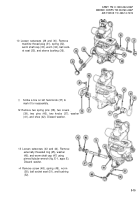
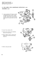
Lightly lubricate shoe (33) and new washer
(34) with grease (item 6, appx D).
Press washer (34) into groove in shoe
(33).
Install shoe (33) on worm shaft (23) with
washer (34) facing outward.
Aline curved side of shoe (33) with curved
side of housing. Press into place.
NOTE
In the following step, knob bearing
scribe mark should be installed on left
end of shaft.
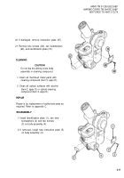
install knob (35) on left end of worm shaft
(23) and aline pin holes with pin holes in
worm shaft.
install knob (36) and aline pin holes with
pin holes in shaft.
install pins (37 and 38).
NOTE
if a new worm shaft was installed,
proceed as follows:
Aline pin holes in two covers (39) with pin
holes (40) in body assembly and install
two spring pins (41). Close covers over
knobs.
ARMY TM 9-1290-262-24&P
MARINE CORPS TM 00476C-24&P
AIR FORCE TO 49A7-3-72/74
37
38
39
40
Push knob (35) on shaft. Leave a clear-
ance of about 0.05 in. (1.27 mm) between
knob and body assembly.
Using hole in knob (35) as a guide, drill a
No. 52 hole in shaft and ream for No. 6/0
pin. install pin (38).
Push knob (36) on shaft. Leave a
clearance of no more than 0.015 inch
between knob and shoe (33).
Using hole in knob (36) as a guide, drill a
No. 52 hole in shaft and ream for No. 6/0
pin. install pin (38).
3-21
Back to Top

