TM-9-1290-262-24-P - Page 53 of 192
65
66
67
68
69
70
71
72
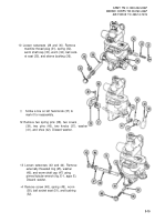
Lightly lubricate 17 stop rings (69) with
grease (item 6, appx D).
Turn worm shaft (59) until elbow telescope
objective end (70) touches body assembly.
Then back off one-half turn.
Install 17 stop rings (69) with tabs pointed
upward and spaced to let rings lie flat.
Install and turn adapter (71) until tab (72)
of top stop rings fits into notch (73) in
adapter.
Turn adapter (71) counterclockwise until it
stops turning.
Back adapter (71) off clockwise until pin
holes are alined and install pin (74).
NOTE
If a new worm was installed, perform steps
71 and 72.
Insert 0.003-inch thickness gage blade
between adapter (71) and top stop ring.
Push down on adapter (71) and using
adapter pin hole as a guide, drill a No. 52
hole in worm shaft (59) and ream for No.
6/0 pin. Install pin (74).
ARMY TM 9-1290-262-24&P
MARINE CORPS TM 00476C-24&P
AIR FORCE TO 49A7-3-72/74
73 Install scale dial (75) and knob (76).
Install two screws (77) loosely. Tightening
will be done during collimation adjust-
ments.
3-25
Back to Top


