TM-9-1290-365-24-P - Page 193 of 334
ARMY TM 9-1290-365-24&P
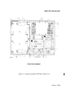
D.4.6.8.2 Configuration AY6707292-5. Refer to Figure D-3.
a. Loosen two screws of connector (27).
b. Loosen two screws of connector (26).
c. Remove 14 screws (28) and 14 flat washers (29) from MVP CCA (25).
d. Remove MVP CCA (25) from transceiver assembly (1) and place it in antistatic bag.
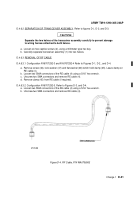
D.4.6.9 REMOVAL OF EMI FILTER MODULE.
D.4.6.9.1 Configuration AY6707292-3 and AY6707292-4 Refer to Figures D-1. and D-2.
a. Remove screw (33) and flat washer (34) which attach clamp (35).
b. Loosen two locks of connector (27).
c. Remove screw (36) and flat washer (37) which attach the EMI filter module (32) to the transceiver
assembly (1).
d. Unscrew protection cap (3) from the external connector.
e. Using connector pliers, loosen and then remove the external connector nut.
f.
Remove the protection cap (3).
g. Remove the EMI filter module (32) from the transceiver assembly (1).
h. Place the connector nut on the connector, and place the module in antistatic bag.
D.4.6.9.2 Configuration AY6707292-5. Refer to Figure D-3.
a. Remove secure wire (43).
b. Unscrew protection cap (3) from the external connector.
c. Using connector pliers, loosen and then remove the external connector nut.
d. Remove the protection cap (3).
e. Remove screw (33) and flat washer (34) which attach clamp (35).
f.
Loosen two locks of connector (27).
g. Remove four screws (52) and four flat washers (53) which attach the EMI filter module (32) to the
transceiver assembly (1).
h. Remove the EMI filter module (32) from the transceiver assembly (1).
i.
Place the connector nut on the connector, and place the module in antistatic bag.
D.4.6.10 REMOVAL OF INTEGRATED SIMULATION ASSEMBLY. Refer to Figures D-2. and D-3.
NOTE
Applies to configurations AY6707292-4 and AY6707292-5 only.
a. Remove three screws (50) and three flat washers (51).
b.
Tag and identify two wires connected to integrated simulation assembly (49).
c. Using extraction tool, remove wire from connector P4 (26), pin 16.
d. Remove solder sleeve that connects wires to connector P4 (26), pin 8.
e. Remove integrated simulation assembly (49) from transceiver assembly (1) and place it in
antistatic bag. Make sure not to damage SMD components.
Change 1
D-23
Back to Top


