TM-9-1290-365-24-P - Page 197 of 334
ARMY TM 9-1290-365-24&P
D.4.12 Testing.
Do not point the radiating surface towards any personnel. Do not bring eyes to
close contact with the radiating surface. Use absorbing materials in front of the
radiating surface whenever possible.
WARNING
NOTE
Hereafter, the transceiver assembly will be referred to as the unit under test (UUT).
D.4.12.1 PREPARATION FOR TEST. The test is conducted on a disassembled UUT, in two major steps,
RF section test (D.4.12.2) and functional test (D.4.12.3)
The test setups are as shown in Figures D-5., D-6, D-7. and D-l1 Figures D-8., D-9., D-10, and D-12
through D-19 are detailed illustrations of the special testers.
a. Disassemble the UUT lAW para. D.4.6.2.
b. Disconnect connector P4 (26 on Figures D-1., D-2. and D-3.) from the MVP CCA (25 on Figures
D-1., D-2. and D-3.).
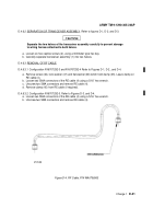
c. Remove the RF cable lAW para. D.4.6.3.
d. Install the RF cable on the transceiver in such a way that its outer edge points out of the
transceiver base.
e. Energize power supply (PS1) and adjust for +28 0.5 Vdc. Deenergize power supply.
f.
Energize power supply (PS2) and adjust both outputs for 12 ± 0.1 Vdc. Deenergize power supply.
g. Energize and adjust digital multimeter (DMM)-1 to measure DC volts.
h. Energize and adjust DMM2 to measure high DC current (10 Amp).
i.
Before connecting the UUT to the test setup, verify that both power supplies are deenergized.
D.4.l2.2 RF SECTION TEST.
D.4.1 2.2.1 RF Section Test Procedures. The test setup provided in Figure D-5, shows the equipment
used and cable hookup for the first procedural step. Refer to Figure D-9. for schematic of the special test
equipment.
D.4.12.2.2 Test Data Sheets. The test data sheets in Table D-5, are to be reproduced locally, as required,
for recording the test results. The test data sheets must be completed each time a test section is
performed. The completed test data sheets shall be retained and used as a troubleshooting aid.
D-27
Back to Top


