TM-9-1290-365-24-P - Page 191 of 334
ARMY TM 9-1290-365-24&P
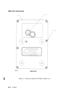
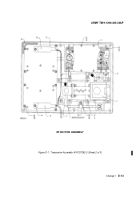
D.4.6.2 SEPARATION OF TRANSCEIVER ASSEMBLY. Refer to figures D-l., D-2. and D-3.
Separate the two halves of the transceiver assembly carefully to prevent damage
to wiring harness attached to both halves.
a. Loosen six hex captive screws (2), using a millimeter type hex key.
b. Carefully separate transceiver assembly (1) into two halves.
D.4.6.3 REMOVAL OF RF CABLE.
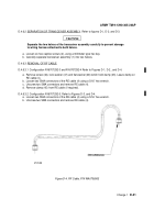
D.4.6.3.1 Configuration AY6707292-3 and AY6707292-4 Refer to Figures D-1, D-2., and D-4.
a. Remove screw (46), lock washer (47) and flat washer (48) which hold clamp (45). Leave clamp on
RE cable (4).
b. Loosen two SMA connectors of the RE cable (4) using a 5/16” hex wrench.
c. Unscrew two SMA connectors and remove RE cable (4).
d. Remove clamp (45) from RE cable (if required).
D.4.6.3.2 Configuration AY6707292-5. Refer to Figures D-3. and D-4.
a. Loosen two SMA connectors of the RE cable (4) using a 5/16” hex wrench.
b. Unscrew two SMA connectors and remove RE cable (4).
CAUTION
M129-08
Figure D-4. RF Cable, P/N WA6706563
Change 1
D-21
Back to Top


