TM-9-1290-365-24-P - Page 204 of 334
ARMY TM 9-1290-365-24&P
m. Verify operating current consumption on current meter DMM2 is 500 ± 200mA.
n. Adjust PS1 output voltage to 28Vdc± 0.5V.
o. Turn off the POWER switch in the test fixture.
D.4.1 2.2.4 Transmitted Frequency Test. The purpose of this test is to ensure the proper accuracy of the
transmitted frequency. Refer to para. D.4.13.2 for troubleshooting procedures.
a. Verify that the frequency counter is properly connected to the directional coupler. Set the
frequency counter to 10GHz measuring range.
b. Set the variable attenuator to 0dB.
c. Turn on the POWER switch of the test fixture.
d. Turn on SD.ANT switch on the test fixture.
e. Wait at least two minutes before performing the frequency measuring.
f.
Verify the transmitted frequency on the frequency counter is 10525 ± 6MHz. After measuring,
adjust the frequency to 10525 ± 1 MHz.
g. Set S.D. ANT and POWER switches on the test fixture to OFF.
D.4.12.2.5
Transmitted Power Test. The purpose of this test is to ensure the proper transmitted power.
Refer to para. D.4.13.3 for troubleshooting procedures.
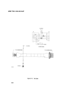
a. Disconnect the frequency counter from the directional coupler. Connect the power meter as
described in Figure D-6. The variable attenuator shall be set to 0dB attenuation.
b. Set POWER and SD.ANT. switches on the test fixture to ON.
c. Measure the transmitted power on the power meter and record the results in mW. Expected power
at the directional coupler port is 1mW to 3mW(OdBm to 5dBm). Set the power meter to the proper
range.
d. Verify the calculated transmitted power in dBm is 22.3± 1.5dBm.
PT(dBm) = Pt(dBm) + KP
where:
PT(dBm)= Transmitted power in dBm
Pt(dBm) = 10xlog [Pt(mW)/i mW]
Pt(mW) is the power measured in step c. above.
KP = Power calibration factor as indicated on the directional coupler.
e. Set SD.ANT. and POWER switches on the test fixture to OFF.
D.4.12.2.6
Receiver Sensitivity Test. The purpose of this test is to ensure the proper receiving sensitivity
of the transceiver unit. Refer to para. D.4.13.4 for troubleshooting procedures.
a. Test Setup
(1) Connect the test equipment as described in Figure D-7.
(2) Set function generator output function to square wave 50±1KHz, 8 ± 0.1Vp-p on output.
(3) Connect oscilloscope CH1 to VIDEO(+) and CH2 to VIDEO(-) outputs on the test fixture.
b. Noise Level Test
(1) Set the variable attenuator to 30± 0.5dB attenuation. Set S.D and ANT. POWER switches on
the test fixture to ON. Set PIN SW DRV/INTERNAL SIM switch to PIN SW DRV position.
(2) Observe the noise level of the video amplifier outputs on both channels of the oscilloscope.
Verify that the signal is broad band noise and there are no oscillations.
(3) Disconnect both channels of the oscilloscope from the test fixture.
(4) Connect the RMS voltmeter input to the VIDEO[+] output on the test fixture.
(5) Verify the noise level in mV: 100mVrms to 300mVrms.
D-34
Back to Top


