TM-9-1290-365-24-P - Page 207 of 334
ARMY TM 9-1290-365-24&P
Date:
_______________________
Tested by:
_______________________
Inspected by: _______________________
D.4.12.3 2.3 FUNCTIONAL TEST.
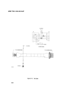
D.4.l2.3.1 2.3.1 Functional Test Procedures. The test setup provided in Figure D-11. shows the
equipment used and cable hookup for the first procedural step.
D.4.12.3.2 Test Data Sheet. The test data sheets in Table D-6., are to be reproduced locally, as required,
for recording the test results. The test data sheets must be completed each time a test section is
performed. The completed test data sheets shall be retained and used as a troubleshooting aid.
D.4.12.3 2.3.3 Preparation for Test.
a. Reinstall the RF cable lAW para. D.4.11.7 .7.
b. Reconnect connector P4 (26 on Figures D-1, D-2. and D-3.) to the MVP CCA (25 on Figures D-1,
D-2. and D-3.).
c. Energize power supply and adjust for +28 ± 0.5Vdc. Deenergize power supply.
d. Energize and adjust DMM to measure high DC current (10A range).
e. Place the test Doppler simulator on the transceiver antenna radome using the handle.
D-37
Back to Top


