TM-9-1290-365-24-P - Page 203 of 334
ARMY TM 9-1290-365-24&P
D.4.12.2.3
Transceiver Power Supply Tests.
NOTE
Power is supplied to the transceiver assembly through the test fixture.
The purpose of this test is to ensure the proper operation of the transceiver assembly for power
consumption and on/off control. Refer to para. D.4.13.1 for troubleshooting procedures.
a. Set POWER and RF CONTROL switches on the test fixture to OFF.
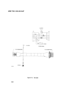
b. Connect the transceiver to the test fixture as described in Figure D-5.
c. Energize both power supplies (PS1, PS2). Turn on the POWER switch on the test fixture.
d. Verify stand by current consumption on current meter DMM2 is 400± 200mA.
e. Connect DMM1 to +5V and GND test points on the test fixture. Verify voltage on DMM1 is +5± 0.1
Vdc.
f.
Connect DMM1 to +15V and GND test points on the test fixture. Verify voltage on DMM1 is +15 ±
O.2Vdc.
g. Connect DMM1 to –15V and GND test points on the test fixture. Verify voltage on DMM1 is -
1±O.2Vdc.
h. Turn on the S.D ANT switch on the test fixture.
i.
Verify operating current consumption on current meter DMM2 is 700 ± 200mA.
j.
Adjust PS1 output voltage to 22Vdc± 0.5V.
k. Verify operating current consumption on current meter DMM2 is 900 ± 200mA.
l.
Adjust PS1 output voltage to 32Vdc±0.5V.
D-33
Back to Top


