TM-9-1290-365-24-P - Page 239 of 334
ARMY TM 9-1290-365-24&P
D.6.11 Testing.
CAUTION
The power supply module contains components subject to damage by electros-
tatic discharge. Use approved grounding procedures before touching, removing,
or inserting CCA.
NOTE
Hereafter, the power supply module will be referred to as the Unit Under Test (UUT).
D.6.11.1 GENERAL.
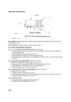
D.6.11.1.1 Power Supply Module Test Procedures. The test setup provided in Figure D-26. shows the
equipment used and cable hookup for the test procedure. Figures D-27. and D-28. are detailed
illustrations of the special testers.
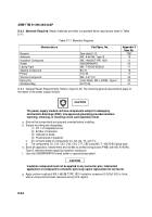
D.6.11.1.2 Test Data Sheets. The test data sheets in Table D-12., are to be reproduced locally, as
required, for recording the test results. The test data sheets must be completed each time a test section is
performed. The completed test data sheets shall be retained and used as a troubleshooting aid.
D.6.11.2 PREPARATION FOR TEST. The test is conducted on a disassembled UUT.
The test setup is shown in Figure D-26. Figures D-27. and D-28. are detailed illustrations of the special
testers.
a. Remove the UUT from higher assembly lAW para. D.4.6.7.
b. Energize and adjust digital multimeter DMM1 to measure DC volts.
c. Energize and adjust DMM2 to measure high DC current (lOAmp).
d. Set switch S1 on the test fixture to PS position.
e. Set ANT S.D switch on the test fixture to OFF position.
f.
Energize and adjust DC power supply to measure +28±1 Vdc. Deenergize DC power supply.
g. Before connecting the UUT to the test setup, verify that the DC power supply is deenergized.
h. Connect the UUT to the test setup lAW Figure D-26.
D.6.11.3 FUNCTIONAL TEST The purpose of this test is to certify and verify that the tested unit is
working without failure. This test is performed whenever calibrating and/or after repairing the power
supply (CCA or module).
D.6.11.3.1 +5V Output Test. Refer to para. D.6.12.1 for troubleshooting procedures.
a. Energize all test equipment.
b. Set switch S1 to position +5V.
c. Verify voltage measurement on DMM1 is 5±0.lVdc.
d. Measure the ripple with the oscilloscope in AC mode. Verify ripple on oscilloscope is less than
5Om Vp-p.
e. Verify current measurement on DMM2 is 850 ± 200mA.
D-69
Back to Top

