TM-9-1290-365-24-P - Page 245 of 334
ARMY TM 9-1290-365-24&P
H. Turn off ANT S.D. switch.
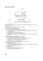
D.6.11.4.3 Selection of Resistors.
a. Deenergize all test equipment.
b. Disconnect clips TP1 and TP2 from the tested unit.
c. Measure with the DMM the resistance between TP1 and TP2 in the test equipment and record in
the adjustment data sheet RM.
d. Choose resistors combination type RLRO5 or RNC5O at least 2% accuracy with the nearest
resistance to the resistance RM. See Table D-13. and record in the data sheet Table D-14.
e. Using soldering iron, solder the chosen resistors R16 & R17 in the UUT.
Table D-13. Resistors Selection List
D.6.11.4.4 Adjustment Test.
a. Energize all test equipment.
b. Turn on ANT S.D. switch.
c. Verify voltage measure in DMM1:
Vout=V±0.1Vdc
(Where V is the desired voltage to the transceiver.)
d. Turn off ANT S.D. switch.
D-75
Back to Top


