TM-9-2320-209-34-2-3 - Page 345 of 592
TM 9-2320-209-34-2-3
FRAME 2
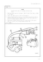
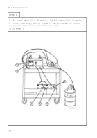
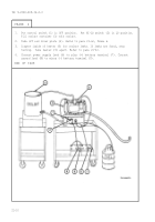
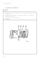
1. Put control switch (1) in OFF position. Put HI-LO switch (2) in LO position.
Fill coolant container (3) with coolant.
2. Take off end cover plate (4). Refer to para 21-6c, frame 6.
3. Inspect inside of heater (5) for coolant leaks. If leaks are found, stop
testing.
Take heater (5) apart. Refer to para 21-6c.
4. Connect power supply lead (6) to plus (+) battery terminal (7). Connect
ground lead (8) to minus (-) battery terminal (9).
END OF TASK
21-10
Back to Top


