TM-9-2320-260-20 - Page 1111 of 1337
TM 9-2320-260-20
I
13-62. TRANSFER PTO CONTROL LINKAGE MAINTENANCE (M815, M819 W/W)
THIS TASK COVERS:
a. Removal
c. Installation
b. Inspection
INITIAL SETUP
APPLICABLE MODELS
REFERENCES (TM)
M815 W/W, M819 W/W
TM 9-2320-260-10
MATERIALS/PARTS
TM 9-2320-260-20P
Four cotter pins
EQUIPMENT CONDITION
Lockwasher
●
Parking brake set (TM 9-2320-260-10).
Woodruff key
●
Driver’s seat removed (para. 11-32).
1.
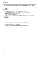
Remove two cotter pins (2), clevis pins (1), and link rod (3) from lever (20) and control lever (5).
Discard cotter pins (2).
2. Remove two cotter pins (12), clevis pins (13), and link rod (14) from lever (11) and power takeoff
shift lever (17). Discard cotter pins (12).
3. Remove nut ( 16), lockwasher (15), screw (10), and lever (11) from shaft ( 19). Discard lockwasher (15).
4. Remove woodruff key (8) from shaft (19). Discard woodruff key (8).
5. Remove lever (20), shaft (19), and spacer (18) from bracket (9).
6. Remove straight pin (4), pin (7), and control lever (5) from bracket (6).
1.
Inspect link rods (3) and (14) for cracks, breaks, and bends. Replace link rod (3) or (14) if damaged.
2. Inspect control lever (5) for cracks, breaks, and bends. Replace control lever (5) if damaged.
3. Inspect levers (11) and (20) for cracks, breaks, and bends. Replace levers (11) and (20) if damaged.
1. Install control lever (5) on bracket (6) with pin (7) and straight pin (4).
2. Install spacer (18), shaft (19), and lever (20) on bracket (9).
3. Position new woodruff key (8) on shaft (19).
4. Install lever (11) on shaft (19) with screw (10), new lockwasher ( 15), and nut ( 16).
5. Install link rod (14) on power takeoff shift lever (17) and lever (11) with two clevis pins (13) and
new cotter pins (12).
6. Install link rod (3) on lever (20) and control lever (5) with two clevis pins (1) and new cotter
pins (2).
13-138
Back to Top


