TM-9-2320-260-34-1 - Page 140 of 657
TM 9-2320-260-34-1
3-24.
ENGINE AND TRANSMISSION REPLACEMENT
(Contd)
c. Installation
1 .
2 .
3.
4.
5.
6.
7.
8 .
WARNING
• All personnel must stand clear during lifting operations.
A stinging or shifting load may cause injury to personnel.
• Lifting device must have a weight capacity greater than 5000 lbs
(2270 kg). Failure to do so may result in injury to personnel
and/or damage to equipment.
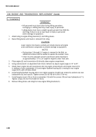
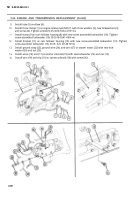
Attach sling to engine lifting brackets (1) and lifting device.
Raise lifting device until slack is removed from sling.
CAUTION
Lower engine into chassis carefully and closely observe all engine
and transmission components to prevent damage to equipment.
NOTE
• During steps 3 through 5, if engine is removed in the field, an
additional assistant will be needed to operate the wrecker crane.
• Chain must be adjusted so that transmission points downward
at approximately a 15° to 20° angle for engine to clear front axle.
Place engine (2) and transmission (6) directly above engine compartment.
Using socket wrench on adjustable hoist chain ratchet (14), adjust engine angle to 15° to 20°.
Slowly lower engine (2) and transmission (6) into engine compartment until engine mount (13)
is resting on front crossmember (12) and engine flywheel housing (5) is resting on rear engine
supports (7), with all holes alined.
Install engine flywheel housing (5) on rear engine supports (7) with two screws (3), washers (4), new
lockwashers (8), and nuts (9). Tighten screws (3) 140-160 lb-ft (190-217 N•m).
Install engine mount (13) on front crossmember (12) with five screws (10) and new lockwashers (11).
Tighten screws (10) 65-75 lb-ft (88-102 N•m).
Remove lifting device and sling from two engine lifting brackets (1).
3-88
Back to Top


