TM-9-2320-260-34-1 - Page 258 of 657
TM 9-2320-260-34-1
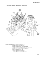
3-69. ACCESSORY DRIVE INSTALLATION
THIS TASK COVERS:
Installation
lNITIAL SETUP
APPLICABLE MODEIS
All
MATERIALS/PARTS
Five screw-assembled lockwashers
TOOLS
(Appendix D, Item 399)
Gasket (Appendix D, Item 109)
General mechanic’s tool kit
(Appendix B, Item 1)
REFERENCES (TM)
Torque wrench, 3/8-in. dr.
(Appendix B, Item 4)
TM 9-2320-260-34P-1
Engine barring tool (Appendix B, Item 66)
Installation
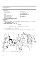
1. Using engine barring tool, rotate engine crankshaft until number one cylinder is at top dead center
(TDC) of compression stroke.
2. Rotate engine crankshaft 90° past TDC.
CAUTION
Accessory drive gear and camshaft gear timing marks must be
properly alined for engine to operate.
3. Remove pipe plug (3) from front gear cover (1).
4. Position new gasket (5) and accessory drive (7) on cylinder block (4), Ensure timing marks on drive
gear (6) are alined with timing marks on camshaft gear (9) in hole (2) on front gear cover (1).
5.
Install accessory drive (7) with five new screw-assembled lockwashers (8).
6. Install pipe plug (3) in front gear cover (1).
7. Tighten screw-assembled lockwashers (8) 40-45 lb-ft (54-61 N-m).
FOLLOW-ON TASKS: l Install air compressor (para. 11-3).
l Install accessory drive pulley (para. 3-70).
3-206
Back to Top


