TM-9-2320-260-34-1 - Page 250 of 657
TM 9-2320-260-34-1
3-63. CROSSHEAD INSTALLATION
THIS TASK COVERS:
Installation
INITIAL SETUP
APPLICABLE MODELS
MATERIALS/PARTS
All
Lubricating oil (Appendix C, Item 21)
TOOLS
REFERENCES (TM)
General mechanic’s tool kit
(Appendix B, Item 1)
TM 9-2320-260-34 P-1
Torque wrench, 3/8-in. dr.
(Appendix B, Item 4)
Dial indicator (Appendix B, Item 11)
Wire gage (Appendix B, Item 94)
Installation
1.
2.
3.
4.
5.
6.
7.
8.
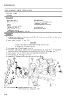
Loosen adjusting screw (2) one full turn.
Install crosshead (3) on guide (5) so crosshead (3) touches valve stem (4) on side opposite adjusting
screw (2).
Turn adjusting screw (2) until it touches valve stem (6).
Position dial indicator over center of crosshead (3). Zero dial indicator.
Holding crosshead (3) down lightly, turn adjusting screw (2) until dial indicator reads 0.020-0.040 in.
(0.51-1.0 mm). Tighten jamnut (1) 22-26 lb-ft (30-35 N•m).
Using wire gage, measure gap (7). Measurement must be a minimum of 0.025 in. (0.64 mm). Loosen
jamnut (1) and turn adjusting screw (2) clockwise. Tighten jamnut (1) 22-26 lb-ft (30-35 N•m).
Repeat step 6 until gap (7) is correct.
Remove dial indicator from cylinder head (8).
3-198
Back to Top


