TM-9-2320-260-34-1 - Page 260 of 657
TM 9-2320-260-34-1
3-71. FRONT GEAR COVER INSTALLATION
THIS TASK COVERS:
Installation
INITIAL SETUP
APPLICABI.E MODELS
MATERIALS/PARTS
All
Two lockwashers (Appendix D, Item 215)
TOOLS
Four lockwashers (Appendix D, Item 217)
Shims (Appendix D, Item 500)
General mechanic’s tool kit
(Appendix B, Item 1)
Gasket (Appendix D, Item 58)
Outside micrometer (Appendix B, Item 8)
REFERENCES (TM)
Feeler gage (Appendix B, Item 58)
TM 9-2320-260-20
TM 9-2320-260-34P-1
Screws securing front gear case cover are different lengths. Ensure
screws are installed in their proper places. Failure to do so may
result in damage to equipment.
Installation
1.
2.
3.
4.
5.
6.
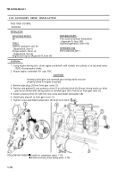
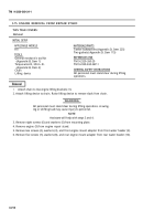
Install new gasket (1) and front gear cover
(6)
on cylinder block (2) with fifteen screws (7), two
washers (10), new lockwashers (9), screws (8), four washers (3), new lockwashers (4), and screws (5).
Remove two screws (15), camshaft cover (14), spacer (11), and shim(s) (12) from front gear cover (6).
Place camshaft cover (14) against camshaft (13) and measure clearance between cover (14) and front
gear cover (6) with feeler gage.
Measure shim(s) (12) as a pack with micrometer. Add or subtract shim(s) (12) from pack to provide
a clearance of 0.001-0.005 in. (0.0254-0.127 mm) for engines with camshaft thrust plate or
0.008-0.013 in. (0.2032-0.3302 mm) for engines with camshaft outboard bearing support.
Install camshaft cover (14), spacer (11), and shim(s) (12) on front gear cover (6) with two
screws (15).
Remove dowel pins (refer to para, 3-33) from cylinder block (2).
3-208
Back to Top


