TM-9-2320-260-34-1 - Page 269 of 657
TM 9-2320-260-34-1
3-77. INTAKE AND EXHAUST VALVES REFACING
THIS TASK, COVERS:
a. Valve Specifications
c. Cleaning After Refacing
b. Grinding or Refacing Valves
INITIAL SETUP
APPLICABLE MODELS
REFERENCES (TM)
All
TM 9-2320-260-34 P-1
TM 9-4910-484-10
TOOLS
General mechanic’s tool kit
EQUIPMENT CONDITION
(Appendix B, Item 1)
Intake and/or exhaust valve(s) removed (para. 3-51).
Valve refacer (Appendix B, Item 41)
Outside micrometer (Appendix B, Item 8)
a. Valve Specifications
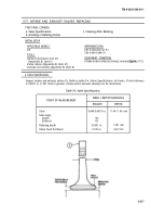
Inspect intake and exhaust valves (1). Refer to table 3-4, Valve Specifications, for limits. If rim thickness
is 0.0591 in. (1.501 mm) or greater, intake and/or exhaust valve(s) can be resurfaced.
Table 3-4. Valve Specifications.
WEAR LIMITS/TOLERANCES
POINT OF MEASUREMENT
ENGLISH
METRIC
Stem
0.449-0.4510 in.
11.40-11.46 mm
Seat angle
Intake
30°
Exhaust
45°
Refacing depth
0.0591 in.
1.501 mm
Valve head thickness
0.105 in.
2.67 mm
3-217
Back to Top


