TM-9-2320-260-34-1 - Page 272 of 657
TM 9-2320-260-34-1
3-78. VALVE SEAT INSERTS MAINTENANCE (Contd)
b. Gaging and Counterboring
CAUTION
Before counterboring, each replacement valve seat insert outside
diameter and thickness must be measured and compared to
relating valve seat insert counterbore in the cylinder head. These
measurements will prevent overboring and damage to the cylinder
head.
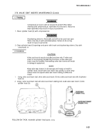
1. Measure valve seat insert (1) outside diameter and thickness. Refer to table 3-5, Valve Seat Insert
Specifications, for measurements. Replace valve seat insert (1) if valve seat insert (1) does not meet
specifications.
2. Measure insert counterbore (2) depth and inside diameter. Refer to table 3-5, Valve Seat Insert
Specifications, for measurements. Perform counterboring procedures if insert counterbore (2) does
not meet specifications.
Table 3-5. Valve Seat Insert Specifkations.
VALVE SEAT INSERT
VALVE SEAT INSERT
INSERT COUNTERBORE
INSERT COUNTERBORE
THICKNESS
OUTSIDE DIAMETER
DEPTH
INSIDE DIAMETER
0.278-0.282
in.
2.0025-2.0035
in.
Standard
1.9995-2.0005 in.
(7.0612-7.1628 mm)
(50.864-50.889
mm)
(50.787-50.813 mm)
NOTE
When using counterbore cutter, center the cutter in the insert
counterbore and valve guide arbor.
Allow counterbore cutter to turn several revolutions at exact
3.
moment the proper depth in cylinder head is reached to ensure
a perfectly flat bottom of bore for valve seats to seat.
Using counterbore cutter and valve guide arbor, cut insert counterbore (2) 0.006-0.010 in.
(0.152-0.254 mm) deeper than valve seat insert (1) thickness. This will allow staking of cylinder
head (3) to secure valve seat insert (1).
3-220
Back to Top

