TM-9-2320-260-34-1 - Page 280 of 657
TM 9-2320-260-34-1
3-80. VALVE SEAT GRINDING
THIS TASK COVERS:
a. Dressing Grinding Wheel
d. Cleaning
b. Pre-Grinding Operation
e. Gaging Valve Seats
c. Valve Seat Grinding
f. Lapping Valve Seats
INITIAL SETUP
APPLICABLE MODELS
REFERENCES (TM)
All
TM 9-2320 -260-34P-1
TOOLS
EQUIPMENT CONDITION
General mechanic’s tool kit
New valve seat insert(s) installed (para. 3-78).
(Appendix B, Item 1)
Dial indicator (Appendix B, Item 11)
GENERAL SAFETY INSTRUCTIONS
Valve guide arbor (Appendix B, Item 44)
l Keep fire extinguisher nearby when using
Valve grinder (Appendix B, Item 62)
drycleaning solvent.
Wire brush (Appendix B, Item 71)
l Compressed air source will not exceed 30 psi
MATERIALS/PARTS
(207 kPa).
l Eyeshields must be worn when cleaning with
Lubricating oil (Appendix C, Item 20)
compressed air.
Drycleaning solvent (Appendix C, Item 48)
l Eyeshields must be worn during grinding
Lint-free cloth (Appendix C, Item 9)
operations.
Prussian blue (Appendix C, Item 26)
Coarse lapping and grinding compound
(Appendix C, Item 18)
Medium lapping and grinding compound
(Appendix C, Item 19)
WARNING
Eyeshields must be worn during grinding operations. Failure to
wear eyeshields may result in injury to personnel.
a. Dressing Grinding Wheel
CAUTION
Intake and exhaust valve seating surface to cylinder head valve
seat is critical. Accurate machining is required to provide for
perfect sealing of combustion chambers.
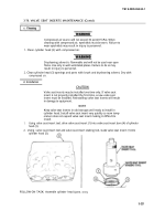
1. Position grinder driver and grinder wheel stone on tool holder stand with grinder wheel stone facing
down.
2. Position tool holder at 30° and lock screw.
3. Position electric grinder motor above angle quadrant, position chuck on grinder driver, and turn
grinder motor switch to “ON” position.
4. Slowly move control handle and draw tool bit across face of grinder wheel stone for test cut.
3-228
Back to Top


