TM-9-2320-260-34-1 - Page 285 of 657
TM 9-2320-260-34-1
3-81. ENGINE INJECTOR TIMING INSTRUCTIONS
THIS TASK COVERS:
a. Timing Tool Setup
b. Injector Timing
INITIAL SETUP
APPLICABLE MODELS
All
TOOLS
General mechanic’s tool kit
(Appendix B, Item 1)
Two dial indicators (Appendix B, Item 11)
Timing fixture (Appendix B, Item 56)
REFERENCES (TM)
TM 9-2320-260-34 P-1
EQUIPMENT CONDITION
Engine mounted on repair stand (para. 3-29).
Rocker lever housing covers removed (para. 3-36).
Rocker lever housing and push tube removed
(para. 3-37).
Crossheads removed (para. 3-39).
a. Timing Tool Setup
NOTE
This timing procedure is for engines mounted on test stand only.
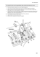
The precise timing of the injector push tube travel with
corresponding piston travel is accomplished by using injector
timing fixture, 3375522, to measure travel of these two parts.
Adjustments to injection timing are made by altering the
thickness of cam follower gaskets or adding or removing cam
follower gaskets.
Ensure camshaft is pushed back against rear of cylinder block
for zero (0) end play.
Each dial indicator used must have a total travel of at least
0.250 in. (6.35 mm).
1.
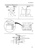
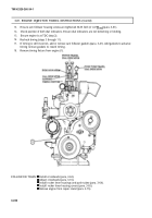
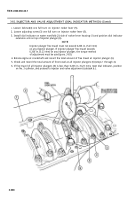
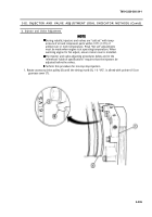
Position timing fixture in injector sleeve (2) and engage rod of push tube indicator in injector push
tube socket.
2.
Install timing fixture by hand tightening knurled holddowns evenly. Ensure timing fixture is
straight on cylinder head (1).
3-233
Back to Top

