TM-9-2320-260-34-1 - Page 294 of 657
TM 9-2320-260-34-1
3-82. INJECTOR AND VALVE ADJUSTMENT (DIAL INDICATOR METHOD) (Contd)
13.
14.
15.
16.
17.
18.
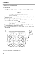
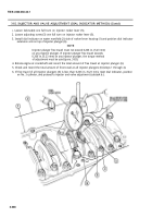
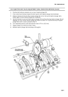
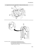
Loosen locknut (1) on intake rocker lever (3) of cylinder No. 5 and back out adjusting screw (2).
NOTE
Clearance for cold-set intake valves is 0.011 in. (0.28 mm).
Clearance for cold-set exhaust valves is 0.027 in. (0.69 mm).
Using feeler gage, measure clearance between intake rocker lever (3) nose and crosshead (4).
Slowly turn adjusting screw (2) until intake rocker lever (3) nose touches feeler gage. There will be
a slight drag on feeler gage when clearance is correct.
NOTE
Ensure adjusting screw does not move when tightening locknut.
When clearance is correct, hold adjusting screw (2) in place with screwdriver and tighen locknut (1)
40-45 lb-ft (54-61 N.m).
Perform adjustment procedures (steps 13 through 16) on exhaust rocker lever.
NOTE
After each set of injector and valve adjustments, advance pulley
to next timing mark and adjust injector and valve until all
timing is complete.
Two complete revolutions of the pulley are required to adjust all
injectors and valves.
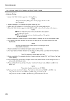
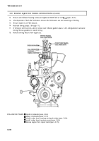
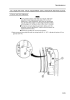
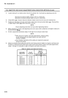
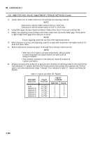
Advance accessory drive pulley (6) until the next timing mark (7) (table 3-6, Injector and Valve Set
Position) is alined with the pointer (8) on gearcase (5) and perform injector and valve adjustments
(steps 1 through 17) indicated in table 3-6, Injector and Valve Set Position.
Table 3-6. Injector and Valve Set Position.
ADJUST
ROTATION
PULLEY
CYLINDER
DIRECTION
POSITION
INJECTOR
I
VALVE
Start
Advance to
Advance to
Advance to
Advance to
Advance to
1-6 "VS"
2-5 "VS"
3-4 "VS"
1-6 "VS"
2-5 "VS"
3-4 "VS"
3
6
2
4
1
5
5
3
6
2
4
1
3-242
Back to Top

