TM-9-2320-260-34-1 - Page 289 of 657
TM 9-2320-260-34-1
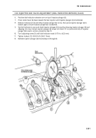
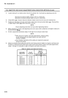
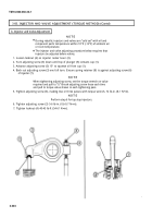
3-82. INJECTOR AND VALVE ADJUSTMENT (DIAL INDICATOR METHOD)
THIS TASK COVERS:
a. Checking Plunger Free Travel
b. Injector and Valve Adjustment
INITIAL SETUP
APPLICABLE MODELS
All
TOOLS
General mechanic’s tool kit
(Appendix B, Item 1)
Injector and valve adjustment kit
(Appendix B, Item 57)
Torque wrench adapter (Appendix B, Item 59)
Dial indicator (Appendix B, Item 11)
Feeler gage (Appendix B, Item 58)
Torque wrench, 1/2-in. dr.
(Appendix B, Item 3)
REFERENCES (TM)
TM 9-2320-260-10
TM 9-2320-260-20
TM 9-2320-260-34P-1
EQUIPMENT CONDITION
l Fuel shutoff valve is in OFF Position
(TM 9-2320-260-10).
l Battery ground cable disconnected
(TM 9-2320-260-20).
l Rocker lever housing covers removed (para. 3-14),
l Valve crossheads adjusted (para. 3-16).
GENERAL SAFETY INSTRUCTIONS
If task is being performed while engine is in vehicle,
ensure fuel shutoff valve is in OFF position and
battery ground cable is disconnected to prevent
engine from starting.
a.
Checking Plunger Free Travel
WARNING
If task is being performed while engine is in vehicle, ensure fuel
shutoff valve is in OFF position and battery ground cable is
disconnected to prevent engine from starting. Failure to do this
may result in injury to personnel.
CAUTION
This procedure is for non-top stop injectors. It is used to prevent
excessive loading of the injector actuating systems and possible
failure.
NOTE
l Loosening all injector rocker lever adjusting screws and locknuts
will help indicate which cylinders have been adjusted and those
cylinders that still need to be adjusted.
l All injectors and valves are adjusted the same. This procedure
covers the injector and valve adjustment for one cylinder head.
3-237
Back to Top


