TM-9-2320-260-34-1 - Page 290 of 657
TM 9-2320-260-34-1
3-82. INJECTOR AND VALVE ADJUSTMENT (DIAL INDICATOR METHOD) (Contd)
I
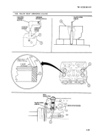
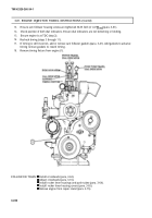
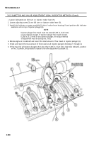
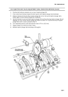
. Loosen locknut(4) one full turn on injector rocker lever (5).
2. Loosen adjusting screw (3) one full turn on injector rocker lever (5).
3. Install dial indicator on water manifold (2) side of rocker lever housing (1) and position dial indicator
extension arm on top of injector plunger (6).
NOTE
Injector plunger free travel must not exceed 0.206 in. (5.23 mm)
on any injector plunger. If injector plunger free travel exceeds
0.206 in. (5.23 mm) on any injector plunger, the torque method
of adjustment must be used (para. 3-83).
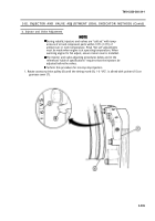
4. Rotate engine at crankshaft and record the total amount of free travel at injector plunger (6).
5. Check and record the total amount of free travel at all injector plungers (6) (steps 1 through 4).
6. If free travel of all injector plungers (6) is less than 0.206 in. (5.23 mm), reset dial indicator, position
on No. 3 cylinder, and proceed to injector and valve adjustment (subtask b.).
3-238
Back to Top


