TM-9-2320-260-34-2 - Page 373 of 863
TM 9-2320-260-34-2
15-83. LOAD CENTER CONDUIT REPLACEMENT
THIS TASK COVERS:
a. Removal
b. Installation
INITIAL SETUP
APPLICABLE MODELS
M820, M820A2
TEST EQUIPMENT
Multimeter (Appendix B, Item 115)
TOOLS
General mechanic’s tool kit
(Appendix B, Item 1)
Tool kit, electrical (Appendix B, Item 106)
Soldering gun (Appendix B, Item 117)
MATERIALS/PARTS
Gasket (Appendix D, Item 76)
Safety wire (Appendix D, Item 372)
MATERIALS/PARTS (Contd)
Electrical tape (Appendix C, Item 51)
Solder (Appendix C, Item 47)
Sealing compound (Appendix C, Item 43)
REFERENCES (TM)
TM 9-2320-260-10
TM 9-2320-260-20
TM 9-2320-260-34P-2
EQUIPMENT CONDITION
●
External power source disconnected
(TM 9-2320-260-10).
●
Battery ground cable disconnected
(TM 9-2320-260-20).
a. Removal
1.
2.
3.
4.
5.
6.
7.
8.
9.
10.
NOTE
Tag wires, cables, and leads for installation.
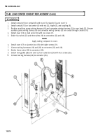
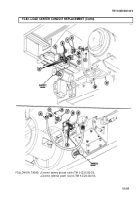
Disconnect wiring harness (7) from connector (1).
Remove four screws (2), cover (3), and gasket (4) from outlet box (5). Discard gasket (4).
Desolder three wires (6) from connector (1).
Disconnect wiring harnesses (12) and (13) from connectors (15) and (11).
Remove eight screws (14) and cover (10) from junction box (8).
Desolder four wires (16) and three wires (9) from connectors (15) and (11).
Remove six screws (17) and cover (29) from load center (22).
CAUTION
Use care when replacing wiring harness. Excessive snagging or
pulling may damage wiring harness.
NOTE
●
Safety wire will be used to install new wiring harness. Do not
cut safety wire from spool until wiring harness has been pulled
through and proper length has been obtained.
●
Safety wire must be attached to wires with electrical tape.
Remove auxiliary pump wiring harness (20) and converter wiring harness (21) from conduit (25).
Remove coupling (24), nipple (19), and nut (18) from load center (22) and conduit (25).
Remove nut (26), nipple (27), nut (28), and conduit (25) from conduit (23).
15-312
Back to Top


