TM-9-2320-260-34-2 - Page 377 of 863
15-84. CONTROL CENTER BOX MAINTENANCE
THIS TASK COVERS:
a. Removal
c. Assembly
b. Disassembly
d. Installation
INITIAL SETUP
APPLICABLE MODELS
M820, M820A2
TEST EQUIPMENT
Multimeter (Appendix B, Item 115)
TOOLS
General mechanic’s tool kit
(Appendix B, Item 1)
Tool kit, electrical (Appendix B, Item 106)
MATERIALS/PARTS
Four lockwashers (Appendix D, Item 224)
REFERENCES (TM)
TM 9-2320-260-10
TM 9-2320-260-20
TM 9-2320-260-34P-2
EQUIPMENT CONDITION
●
External power source disconnected
(TM 9-2320-260-10).
●
Battery ground cable disconnected
(TM 9-2320-260-20).
●
Heater thermostat and 10 kW heater thermostat
removed (TM 9-2320-260-20).
●
AC manual starter switches removed
(para. 15-89).
NOTE
Tag wires, cables, and leads for installation.
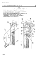
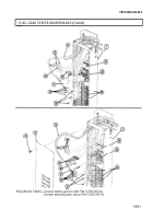
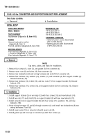
1. Remove eight screws (4) and covers (5) and (7) from control center box (10).
2. Remove three screws (3) and wires (2) from terminal board (1).
3. Remove three screws (6) and wires (8) from circuit breaker (9).
CAUTION
Use care when removing wiring harness. Excessive snagging or
pulling may damage wiring harness.
4. Pull wiring harnesses (14) and (15) through control center box (10).
5. Remove four screws (12), lockwashers (11), and control center box (10) from van body (13). Discard
lockwashers (11).
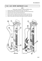
1. Remove three screws (16) and wires (18) from terminal board (1).
2. Loosen three screws (17) and remove three wires (18) from circuit breaker (9).
3. Remove four screws (23) and terminal board (1) from control center box (10).
4. Remove circuit breaker (9) from circuit breaker mounting base (21).
5. Remove two screws (22) and circuit breaker mounting base (21) from control center box (10).
6. Remove two nuts (20) and nipples (19) from control center box (10).
15-316
TM 9-2320-260-34-2
Back to Top

