TM-9-2320-260-34-2 - Page 389 of 863
15-88. OUTLET BOX REPLACEMENT
THIS TASK COVERS:
a. Removal
b. Installation
INITIAL SETUP
APPLICABLE
MODELS
M820, M820A2
TEST EQUIPMENT
Multimeter (Appendix B, Item 115)
TOOLS
General mechanic’s tool kit
(Appendix B, Item 1)
Tool kit, electrical (Appendix B, Item 106)
Soldering gun (Appendix B, Item 117)
MATERIALS/PARTS
Gasket (Appendix D, Item 76)
Four locknuts (Appendix D, Item 182)
Solder (Appendix C, Item 47)
REFERENCES (TM)
TM 9-2320-260-10
TM 9-2320-260-20
TM 9-2320-260-34P-2
EQUIPMENT CONDITION
●
External power source disconnected
(TM 9-2320-260-10).
●
Battery ground cable disconnected
(TM 9-2320-260-20).
NOTE
Tag wires, cables, and leads for installation.
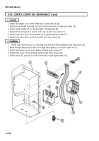
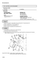
1. Disconnect auxiliary pump wiring harness (1) from connector (2).
2. Remove four screws (3), cover (4), and gasket (5) from outlet box (6). Discard gasket (5).
3. Desolder three wires (8) from connector (2).
4. Remove four locknuts (12), screws (13), and connector (2) from cover (4). Discard locknuts (12).
5. Remove nut (11) from conduit (9) and outlet box (6).
6. Remove two screws (10) and outlet box (6) from van body (7).
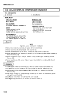
1. Slide outlet box (6) onto end of conduit (9), secure outlet box (6) to conduit (9) with nut (11), and
route wires (8) through hole in outlet box (6).
2. Install connector (2) on cover (4) with four screws (13) and new locknuts (12).
3. Position new gasket (5) and cover (4) on outlet box (6) and solder three wires (8) on connector (2).
4. Install new gasket (5) and cover (4) on outlet box (6) with four screws (3).
5. Install auxiliary pump wiring harness (1) on connector (2).
15-328
TM 9-2320-260-34-2
Back to Top

